

Multi-Chassis Link Aggregation (MCLAG) lets a server bond two NICs to two different switches and still see a single LACP partner. You get switch-level redundancy without spanning tree blocking half your links.
This series builds the smallest MCLAG design that is still useful: two SONiC leaves and two dual-homed hosts. In this part we design it: the topology, the addressing, and the decisions behind them. Later parts build it by hand, automate it, and break it on purpose.
The moving parts#
| Term | What it is in this lab |
|---|---|
| MCLAG domain | The pair of leaves acting as one LACP partner. We use domain 1. |
| Peer-link | PortChannel0001 between leaf1 and leaf2. It carries host traffic that must cross between peers, plus the ICCP session. |
| ICCP | Inter-Chassis Communication Protocol. In SONiC it runs in the iccpd container over TCP port 8888, syncing state (LACP, MAC, ARP) between the peers. |
| MCLAG member | A host-facing port channel that is configured on both leaves: PortChannel0002 (host1) and PortChannel0003 (host2). |
| Unique IP | A VLAN interface that has a different IP on each peer. We use one for the ICCP VLAN. |
Topology#
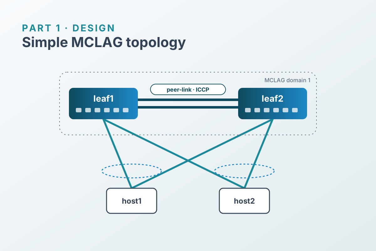
Both leaves use the same port numbering, which keeps the configuration symmetrical:
| Leaf port | Connects to | Port channel |
|---|---|---|
Ethernet0, Ethernet4 | the other leaf | PortChannel0001 (peer-link) |
Ethernet8 | host1 | PortChannel0002 (MCLAG member) |
Ethernet12 | host2 | PortChannel0003 (MCLAG member) |
Addressing#
| Item | leaf1 | leaf2 |
|---|---|---|
| ICCP VLAN | Vlan4094 | Vlan4094 |
| ICCP address (unique IP) | 192.168.255.1/30 | 192.168.255.2/30 |
| Host VLAN | Vlan10 (L2 only) | Vlan10 (L2 only) |
| Host | Address on bond0 |
|---|---|
| host1 | 10.10.10.101/24 |
| host2 | 10.10.10.102/24 |
Vlan10 has no IP on either leaf. Keeping the host VLAN pure layer 2 lets us focus on MCLAG itself. Adding a gateway is a follow-on post.
Design decisions#
Run ICCP over a VLAN on the peer-link#
ICCP needs IP reachability between the peers. The simplest option that needs no extra cabling is a dedicated VLAN (4094) tagged on the peer-link, with a /30 between the two leaves.
That VLAN interface has a different address on each leaf, so it must be marked as a unique IP interface. By default, MCLAG assumes VLAN interfaces are mirrored on both peers.
Make the peer-link a port channel#
The peer-link carries ICCP and any traffic that lands on the “wrong” leaf, such as flooded frames or traffic to a host whose link to the other leaf is down. Size it for a realistic failure case, not the steady state. Even in a lab, two members show how the bundle behaves when one fails.
Keep member names identical on both leaves#
Each host’s port channel has the same name on both leaves (PortChannel0002 for host1, PortChannel0003 for host2). Symmetrical configuration is easier to read and diff, and much easier to template in Part 3.
Hosts run plain LACP#
The hosts need nothing MCLAG-specific: a Linux bond0 in 802.3ad mode. If MCLAG is working, both leaves present the same LACP partner, and the host puts both links in one aggregator. If MCLAG is broken, the host sees two different partners. That symptom is the first thing to check in Part 4.
What we’re not covering (yet)#
- A layer-3 gateway on
Vlan10. That brings in the MAC/ARP sync and gateway behavior that deserves its own post. - EVPN multihoming. It’s the standards-based alternative to MCLAG in VXLAN fabrics.
- Uplinks to spines. This lab is a single leaf pair.